3D Modeling and Remixing using Fusion360 - Sound-Controlled LED Light
Creating a custom enclosure for a sound-controlled LED light using Fusion360, including 3D modeling, 3D printing, and electronics integration.
3D Modeling and Remixing using Fusion360
The Process
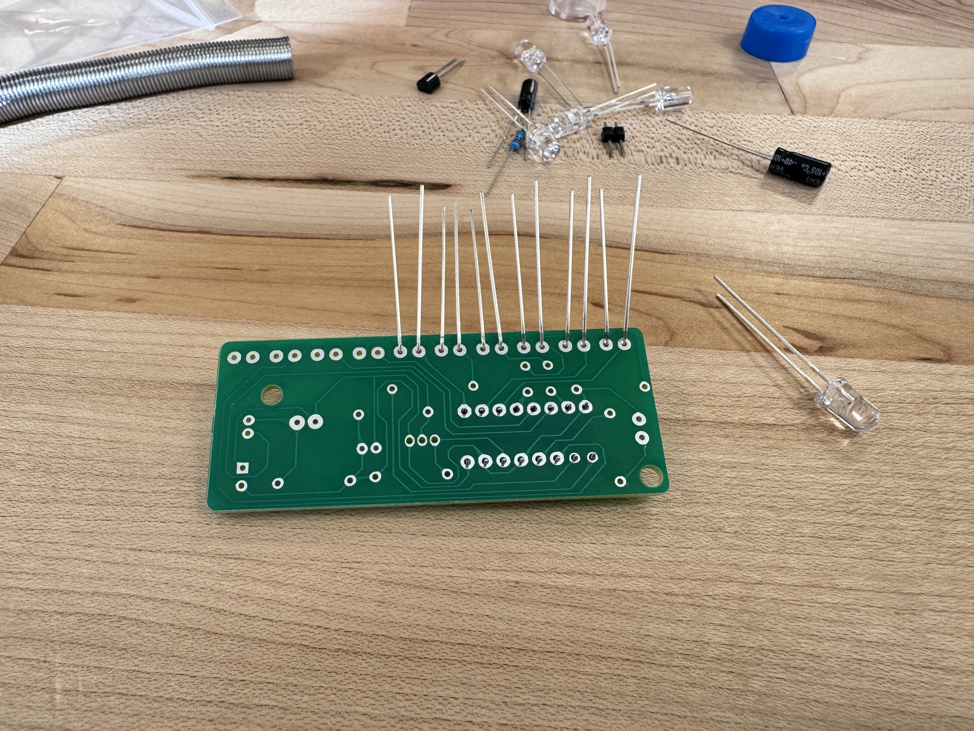
For project 3, we were tasked with creating a sound-controlled LED light. The LEDs should flicker when sound is detected through the microphone component. We were provided with all the necessary parts, and I began the assembly process by heating up the soldering iron.
I started by inserting the LEDs, making sure to orient the positive legs (the longer ones) in the correct direction. Then I placed the soldering iron on both the pad and the legs, heating them up before applying solder. I like to move the iron along the legs to remove any sharp tips that might form. I applied this technique to all components. I encountered some difficulty soldering the battery case wires to the main component, so I attached them to the bottom soldering pads instead.
Designing the Enclosure
For the case design, I first created a sketch in my notebook, planning to glue all the components together after the 3D printing was complete. My measurements were precise, and I allocated 2mm thickness for each side of the boxes.
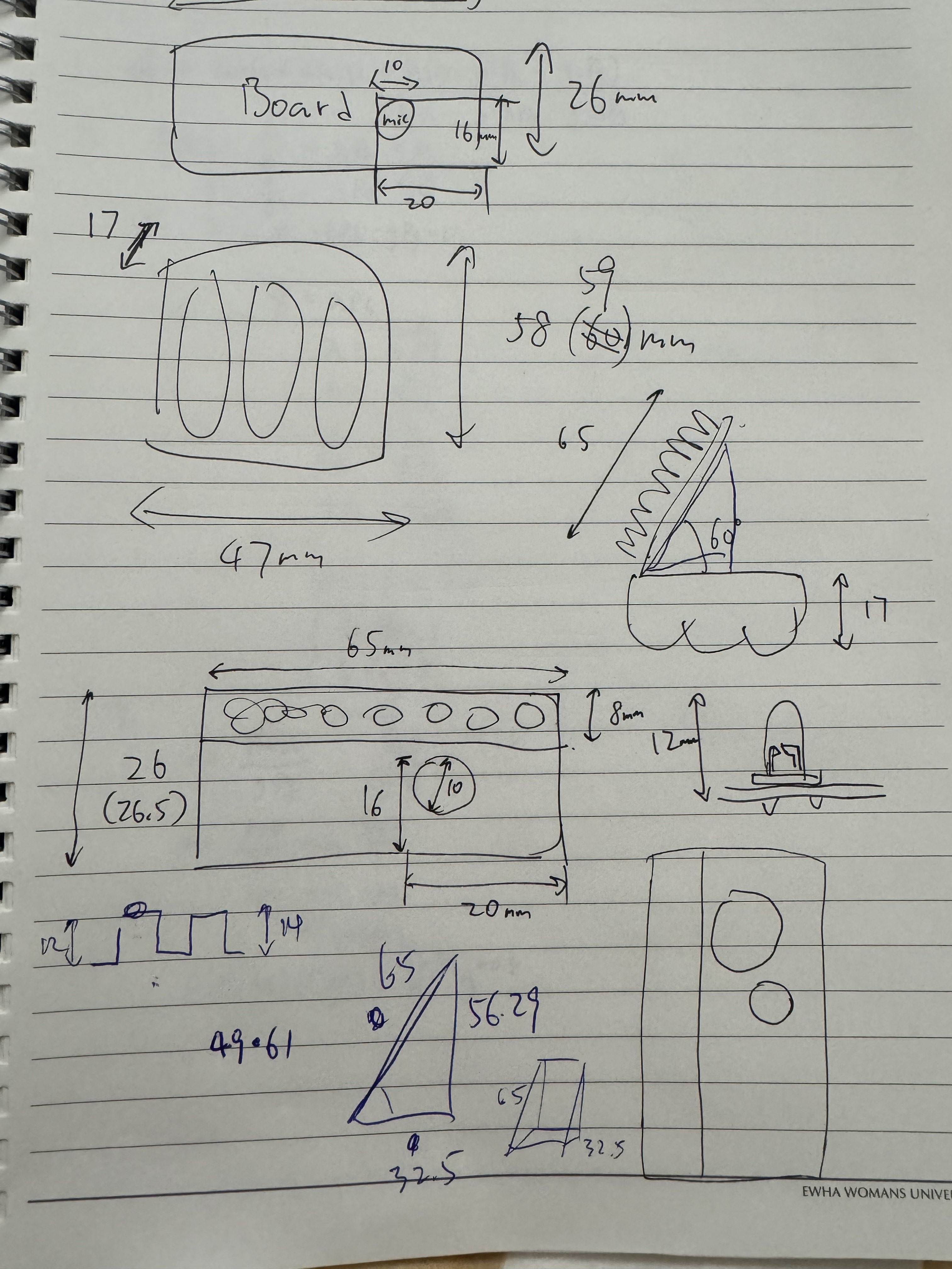
When creating the 3D models, I added 2mm to each dimension of the print. However, I made a critical error - I forgot to add the extra 2mm to each side of the PCB holder, which caused significant issues during assembly.
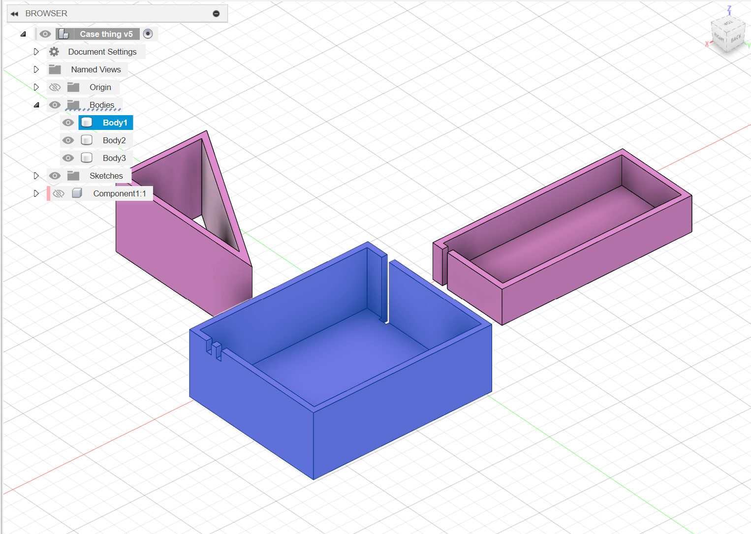
3D Modeling in Fusion360
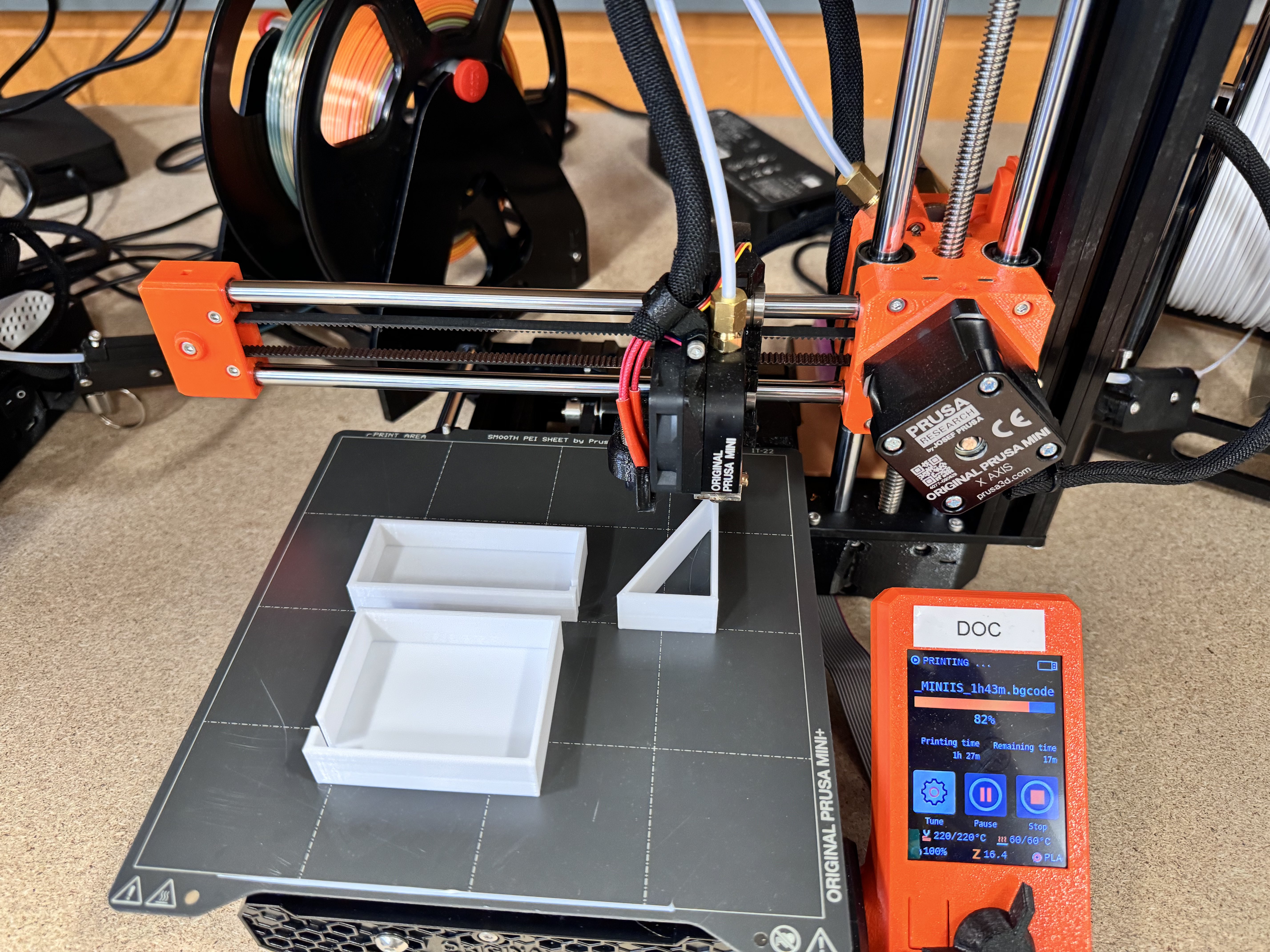
I utilized Fusion360's extrude tool and hole tool to create the three main parts of the enclosure. The modeling process was straightforward, but my dimensional oversight would prove problematic.
The First Print - Learning from Mistakes
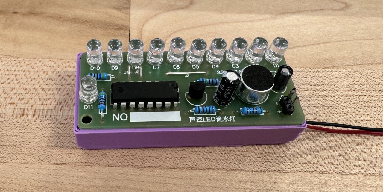
The first printed box was 2mm too small on each side, preventing the PCB from fitting properly. This was a direct result of my earlier measurement error.
Problem-Solving Approach
Rather than redesigning the entire model, I decided to use a practical solution. I imported all the parts into Prusa Slicer and scaled the problematic PCB holder to 110%. This quick fix would accommodate the missing 2mm on each side.
Lessons Learned
Sometimes I find it more effective to implement a simple solution rather than starting from scratch. If the quick fix doesn't work, then I can always return to the drawing board. This approach allows me to learn through iteration and practical problem-solving.
This project taught me the importance of careful measurement and the value of prototyping. While my initial design had flaws, the ability to quickly adapt and modify using both CAD software and slicer settings demonstrates the flexibility of modern 3D design workflows.
The sound-controlled LED light project successfully combined electronics, 3D modeling, and manufacturing techniques, providing valuable hands-on experience in integrated product development.