Pure 3D-Printed Mechanical Counter - Bonus Project
Building a complex 7-segment mechanical counter entirely from 3D printed parts, exploring intricate gear mechanisms, ratchet systems, and precision assembly techniques.
Pure 3D-Printed Mechanical Counter - Bonus Project
Introduction to the Bonus Project
For the bonus project, my classmates suggested recreating something like the e-Nabled hand from a previous assignment. However, I was looking for a project that required less preparation time and didn't involve ordering specialized kits from Amazon. While browsing printables.com, I discovered a fascinating project that immediately captured my attention.
Project Choice: Pure 3D-Printed Mechanical Counter
I found the Pure 3D-printed mechanical counter and was immediately captivated by its complex design and intricate mechanisms. The engineering behind this 7-segment display counter amazed me, and I knew I had to build one myself. I downloaded the files and began the printing process.
Printing Process and Challenges
The project files included components that needed multiple copies while others required only single prints. The parts were quite similar, which led to some confusion during the slicing process, resulting in multiple failed attempts and reprints.
One significant challenge was color coordination - the color of specific parts was crucial for proper operation, but this wasn't clearly marked in the files. This caused most of my initial problems. After several attempts and learning from mistakes, I finally got it right.
Here are all the printed parts laid out for assembly:
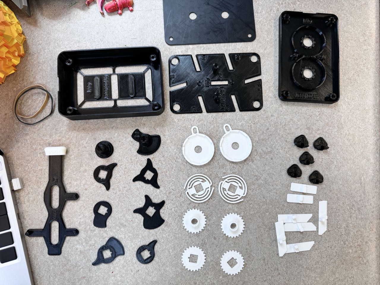
The counter consists of several main components:
- Front casing where all components are housed
- Display plate to hide numbers and mechanism
- Mid plate that holds the cogwheels
- Back plate housing the ratchet mechanism
Assembly Process
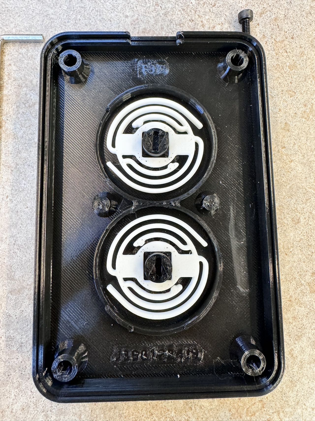
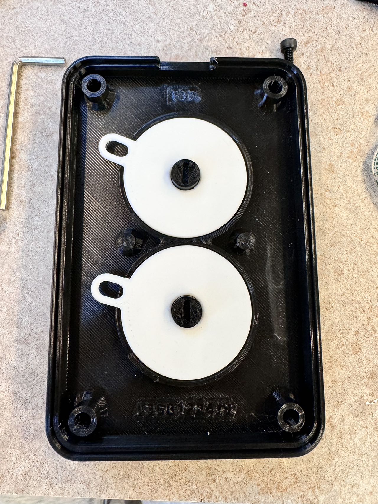
The Number Display System
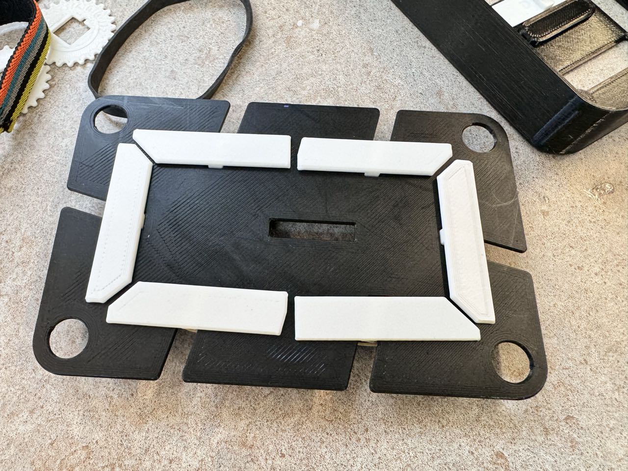
The white number strips proved to be the most time-consuming component to perfect. I spent approximately 3 hours calibrating this system to ensure the small black triangles moved smoothly when pushed by the CAMs (explained below).
Initially, I followed the author's suggestion to use superglue for attaching the triangles to the white strips. However, not having superglue available, I attempted to use hot glue instead. This proved to be a poor decision - the hot glue was too thick and caused dimensional changes that prevented smooth movement. I learned that hot glue is terrible for precision work, especially when you need neat, precise results. Additionally, bringing the glue gun too close to PLA parts caused unwanted melting.
Eventually, I had to clean everything and redo the assembly with superglue, which produced much better results. The numbers are held in position through a slight track that allows them to slide smoothly.
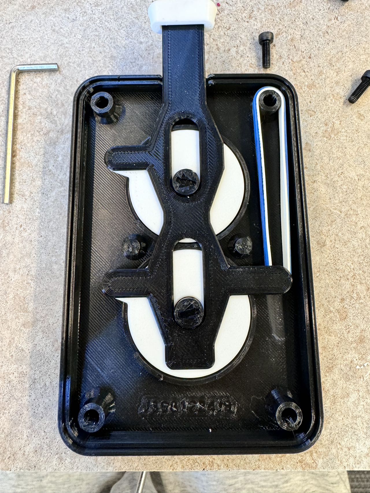
Here's the backside of the number plate:
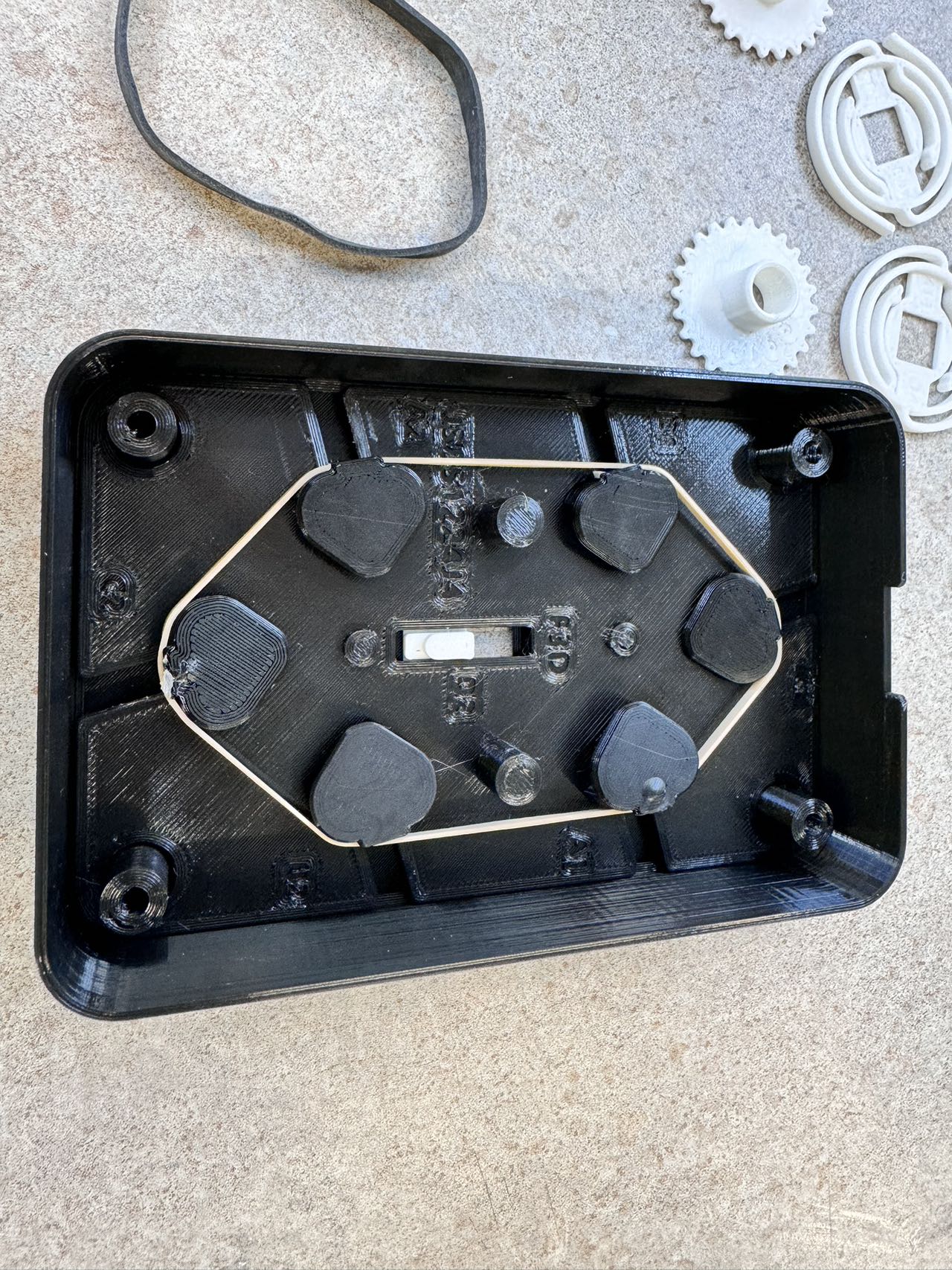
The entire system is held in place with a single thin rubber band that provides just enough tension to keep the strips in position while allowing the CAMs to push them out easily.
The CAM System
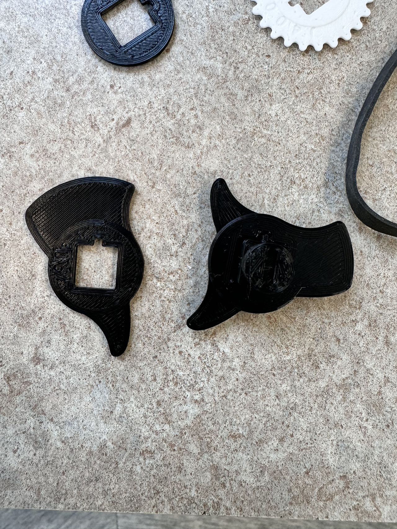
The CAMs represent the most complex and critical part of the entire design. They are stacked on top of each other around a main CAM with a square pole in the center. Additional CAMs are mounted on this square pole and held in place by the mid plate, which has a precisely sized hole that applies downward pressure to keep all CAMs properly aligned.
These CAMs rotate and push the white strips to form the display numbers. In my opinion, this is the most ingenious part of the design and also the most challenging to assemble correctly, as the heights must align perfectly.
Here's the CAM stack assembly:
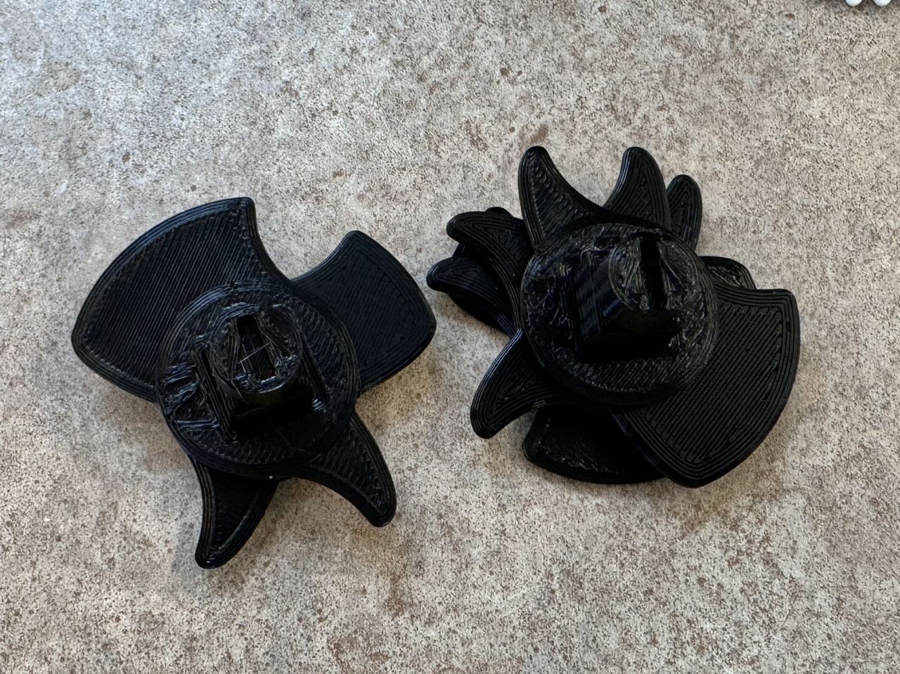
While the CAMs could be printed as a single body, the author chose to separate them for stronger structural integrity and higher customizability. The shape of individual CAMs determines how the white strips interact with each other. When I reached this point in the assembly, I couldn't help but smile at the cleverness of the design - so simple, yet so effective.
Cogs and Alignment
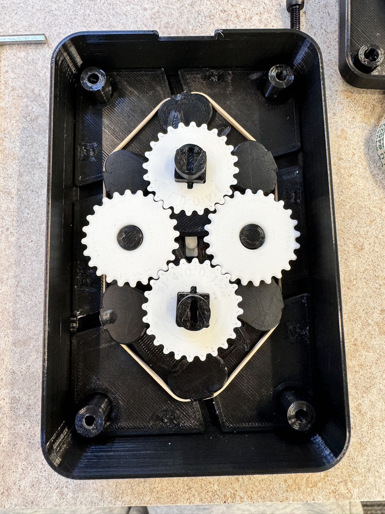
The cogs fit onto the square poles and serve a crucial function - they keep the two rotating CAM systems synchronized to display proper numbers rather than random shapes. This is where precision becomes critical for proper operation.
Mid and Back Plate Installation
Springs and Ratchet Caps
The ratchet mechanism housing begins with springs that work in conjunction with their caps to prevent the bottom poles from rotating backwards after each press. For every rotation, the ratchet pushes down on the caps, rotating them downward against the spring tension. When the ratchet returns to its original position, the internal grooves prevent the springs from returning, ensuring unidirectional movement and preventing back-and-forth motion.
Here are the caps installed:
Final Ratchet Installation
I used two rubber bands to strengthen the ratchet mechanism, providing smoother and more responsive operation. This significantly reduced the return time and improved overall performance. The ratchet mechanism is the most satisfying part of the design to operate.
After completing several test runs, I noticed the white strips didn't completely "hide" to the side when necessary, especially when multiple strips needed to be concealed simultaneously. I believe this was due to the first rubber band being too tight. I searched the Makerlab for a looser alternative, even checking the "finished prints" box for used rubber bands, but couldn't find a suitable replacement.
With assembly complete, I installed the back plate:
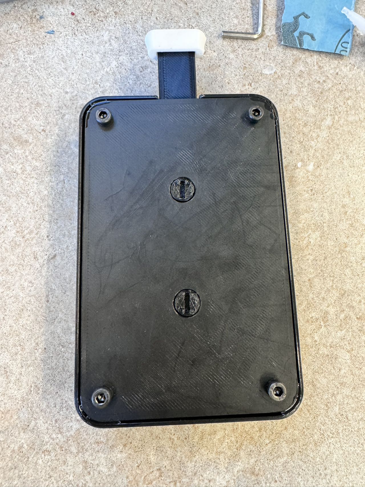
The back plate installation presented its own challenges. The screw holes were designed for #8 wood screws, which I didn't have available. I used M4 screws from the Makerlab as they had the closest diameter to #8 screws. However, these had flat heads and didn't seat properly, so I used a large screwdriver to carefully enlarge the holes. While this was somewhat tedious, it worked effectively.
Final Result
Here's the mechanical counter in operation:
Project Summary
This project was incredibly rewarding to work on due to its complexity and engaging nature. I learned valuable lessons about:
- Mechanism Design: Understanding how complex mechanical systems work together
- Precision Assembly: The importance of exact measurements and careful calibration
- Material Selection: Choosing appropriate adhesives and materials for specific applications
- Problem-Solving: Adapting when exact components aren't available
- Asking for Help: The value of seeking assistance when needed (thanks Harrison!)
The 7-segment mechanical counter project successfully demonstrated that complex mechanical systems can be entirely 3D printed, opening up possibilities for accessible manufacturing of intricate devices. The combination of clever engineering, precise manufacturing, and careful assembly created a fully functional mechanical display that operates purely through physical mechanisms - no electronics required.
This project reinforced my appreciation for mechanical engineering and the potential of 3D printing for creating complex, functional mechanisms. The iterative problem-solving process and attention to detail required made this one of the most challenging and educational projects I've completed.